Remote Trigger Wiring for Contact Enclosure

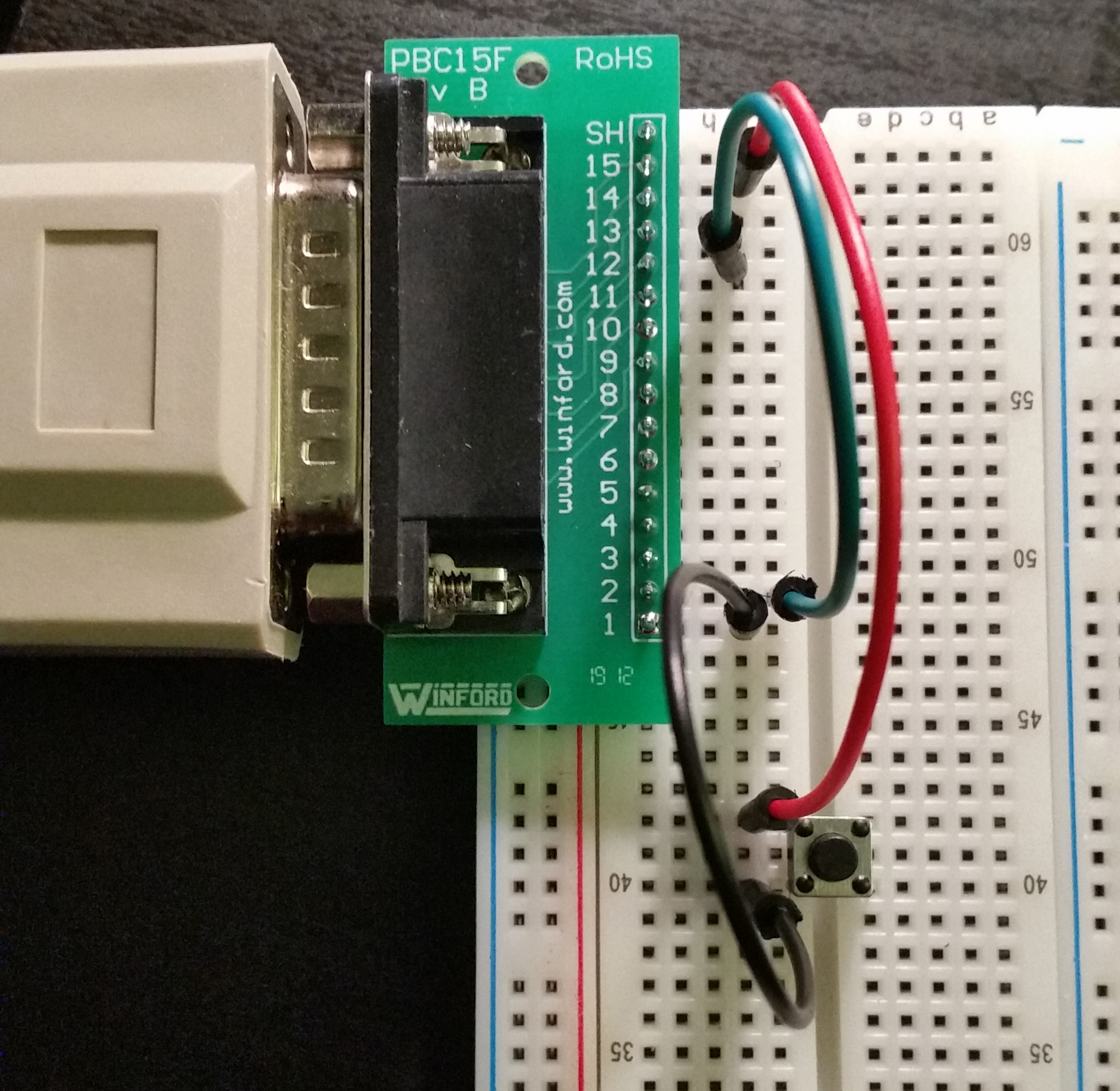
I've got a little breadboard setup and thought I'd post the photo of how to wire up the Remote Trigger ports on the back for Switches 1 - 4. 

This is just showing Switch 1. 

  • Pin 1 (Switch 1) goes to one side of your physical button/switch/trigger
  • Other side of physical button/switch goes to Pin 15 (+12Vdc)
  • Pin 2 goes to Ground Pin 12

To build out all 4 switches, use Pin 14 (+12Vdc) and Pin 12 (Ground) to power Switch 1 & 2.

Use Pin 15 and 13 for Switches 3 & 4. 

EOS v2.6 reference for wiring can be found in RevC of the Show Control manual.

  • I’ve been scouring the forum and Facebook to make sure I understand what’s going on with this contact closure before I buy some parts and start trying to make my own.

    To make sure I understand correctly, to make a remote trigger for switch 1 all I’d need to send down the cable going to what ever device I use to cause a short is pin 1 and 14. I can connect pin 2 to 12 at any point without having to send them down the cable, correct? The 1 to 14 makes sense in DC circuit world, the 2 to 12 is what keeps throwing me as I don’t understand its doing (unless it’s for comparison). I’m looking to use 3 pin XLR as extension headers to the switch, as there is a lot of it hanging around rental shops these days. However if for some reason I have to send all 4 pins down the line I’ll have to rethink.
  • That is correct.  You only need to send Pin 1 (for switch 1) and Pin14 (+12Vdc) down the line to your trigger device.  The physical switch that you use (like a wall switch) merely connects the +12Vdc to Pin 1 only, completing the + side of the circuit.  But then you need to connect Pin 2 to Ground to complete the minus side of the circuit.  You can bond Pin 2 to Pin 12 (Ground) at the console, or in the DB connector itself if you like soldering at the micro level (painful!!).  See page 12 of the ShowControl manual for the DB15 wiring diagram from my first post.

    Initially I was confused like you, that's why I got a breadboard to test it out.  My solution was to buy a DB15 extension cable, cut it in half, and wire the Switch pins and +12Vdc pins to RJ45 female connectors in a Jbox.  I bonded the minus side pins to the ground pins with a wire nut in the the Jbox. Now I can run cat5 to the set and have all 4 switches available.  Get a SPDT wall switch for an easy "lights on" & "lights off" Cue list. Works great!

  • Thank you for the clarification. Very helpful
  • Here is the box I wired up.  Each jack has triggers 1-4 (aka switches 1-4) over a single cat5 cable.  Maybe it's overkill, but this allows me to have the 4 triggers run to different locations just so I have the option of using them where I need them without moving a single cable around from set to set. 

    But essentially you could use just one RJ45 jack and run a single ethernet cable containing all 4 triggers.  I tied pins 2, 4, 6, & 8 to pins 12 & 13 with a wire nut inside the box.  So only the switch pins and +12Vdc pins travel over the ethernet cable, making it perfect for all 4 triggers on one cable.

    I've tested this with a 100-ft db15 extension cable and 50ft cat5 from the box to a wall switch.  Works great!

Related