Augment3D - Linked Positions
I recently ran into a situation where I wanted to limit the travel of an SEM and couldn't find the info on how to do it. Here's a small guide that I have put together to hopefully help with that.
You’re beginning work on a new show, and the producers have allocated some budget for PreViz... the show has some automated positions that will be re-trimmed during the show and you want to be able to control the positions from within the console. Usually, you’d just link them to a Scenic Element Movable (SEM) and be done, but you aren’t using A3D to previz, you’re using an external program like Capture.
I want to talk about limiting the movement range of SEMs, so that you are able to move your fixtures in only the axis they need to, without being able to accidentally move them. Coincidentally, this will also allow you to make a multipart fixture that contains both an SEM and a Capture Mover so that one channel will be able to control both A3D and Capture and have the output scaled correctly.
Determining Trim Height:
Your first electric in your show is going to travel between 14’ and 30’ and could stop anywhere in between, depending on your needs; however, the position can also reach the deck for maintainance, we should let the A3D SEM cover the whole range, because using additional software (such as lightstrike) we can feed the console data about where the position is, and have the A3D model update in the space as the positions change trim, but that’s a topic for another day.
For the purposes of this article, the position can’t fly out higher than 30’ because there’s a mother truss above it. Our first step will be converting feet to meters... in the case of this example, 30’-0” = 9.14m. If you’re following along in non-freedom units, you just need to convert your trim from mm to meters. Why meters? Despite setting your own system of coordinates in Eos setup, all fixture profiles that relate to the SEM are still doing the math in meters.
Now that we have the conversion, we’re going to separately need to convert meters into DMX - I made a fixture profile in the console that contained 16 Bit XYZ focus values so that I could easily punch in whatever data I needed to. It was setup as follows:

Each range was configured to match the default SEM profile (User values of -10000 thru 10000 and the full range of a 16 bit address)

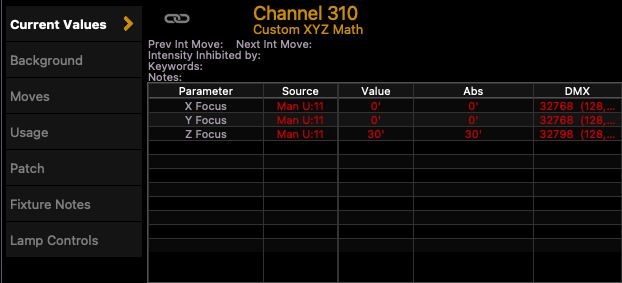
I now key in the trim height I want, in this case 30’ (using feet again because Eos is doing the conversion on the user facing side).
Using the about key, I can see what my DMX offset should be (32798).
You can also do this outside of the console by doing some math, but let’s use the console as our calculator.

Next, in the fixture editor, you should create a copy of the SEM and label it whatever your heart desires. In this case, for clarity and organization, I’m going to call it * 1 ELECTRIC SEM (Calibrated)
Once copied and re-labeled, save the change, you’ll see the following:

We’re going to be adjusting the ranges here. This position has one axis of freedom, meaning that it can only move up and down and all rigging points are linked (the position cannot rotate). So we’re going to start out by preventing ourselves from being able to rotate and move the position US/DS and SL/SR. (You can use the same concept for limiting the motion in a different axis (like for a deck track).

For any axis (of movement or rotation) that you would like to remain static, you must change the following fields to match.
For our Z axis, we want the position to be in its highest trim by default (home position) and have the range such that it’s from 0’ of the automation system (which, yes, will put your lights in the deck) to 30’. Being linked up to the automation system and having all your values mapped correctly will let you be able to easily LightStrike your positions if you chose to.

Exit the range, save the fixture, and patch it to a channel.
Now that you have done this all, putting this SEM into A3D and attaching your first electric lights and geometry to it should allow you to be able to only control the Z height within the specified range.
Thanks for reading :)
