Synching Beams

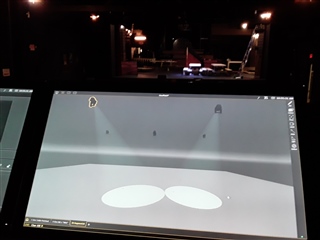
What is the process to synch the beams on stage with those in Augment3d? In the picture I've driven two ML's to hit the same spot (a bench center downstage) on the stage. Back in Augment3 the two beams miss each other.


  • Hi ,

    Augment3d relies on accuracy of the data input into the model as well as the fixture profile data in order to calculate where the beams are in the 3D world as compared to reality. Not only must the locations of your fixtures be precise in your model, but Augment3d must have an exacting understanding of the fixture kinematics (the way the fixture moves) as well.

    I see from your screenshot that your model of your fixture is quite off from what I would expect. If these fixtures are from a previous show file, I recommend that you update your fixture profiles as your first step. See https://support.etcconnect.com/ETC/Consoles/Augment3d/Eos_Fixture_Profiles_must_be_up-to-date_for_Augment3d_Functionality

    From your previous posts, I see you have also been experimenting with building your own profile. If these fixtures are those profiles, please see the instructions for how to determine and correct Pan and Tilt ranges here:https://support.etcconnect.com/ETC/Consoles/Augment3d/Fixture_Physically_Pans_or_Tilts_in_the_Opposite_Direction_from_Visualized_Movement#Pan_Range

    Additionally, you will wish to correct the Hang to Focus offsets in the model definition (this is why the fixture head appears outside of the yoke in the image) by adjusting the values to match the physical measurements of the fixtures. More info on this can be found here: https://support.etcconnect.com/ETC/Consoles/Augment3d/Hang_to_Focus_Offsets

  • Wonderful. One reason I had to build my own is because the lamps I have "Ridgeyard 30 x 10" and some Lixadas actual parameter channel lists in the library do not match my fixtures. So I need be careful to give my home brews different names. I am off to theater for stage work now and going to measure exactly where those lights are. You have provided some great reading for tonight. But can I push my luck here?

    My 1st attempt at P&T (not even on Augment3d) went all of the place. I found that by adjusting the DMX Home value in the profile I could skew the beam to point up stage when I asked. Now: I do have an article that describes a method of swinging the beam around and using [About] to find the DMX values at 90, 180, 360 etc but the terms 'Min value' and especially 'Found Values; seem a bit ambiguous to me. Do you have a better description of how, given e new mover you want accurately set up the min, home and max values in a profile. My 'skewed home' of course places what should be the center of the 0 > 64K range off center. Does that make sense?    

  • Your question does make sense and I'll attempt to clear up the ambiguity. I have realized that the process above has an error in the description. Where it says that it is calculating DMX values, it is actually calculating user range values to correspond with the raw values. I will get that corrected in the support article and flagged for correction in the next revision of the manual.

    We typically assume that 0 degrees is the user range home value of the fixture. From there it might pan or tilt in a positive or negative direction. In a perfectly symmetrical fixture, your range might be something like -270 Pan (0) to +270 Pan (65535) where 0 is exactly in the middle (32768/65535).

    Here is an example of the formula steps that would calculate that -270 and 270 if we didn't already know that value:

    1. Tilt the fixture head away from the user interface so the optics are perpendicular to the yoke (+90deg) and pan until the optics are pointing in exactly the opposite direction. For our perfectly symmetrical fixture, that value would be the default home value of 32768. This is our "Pan 0 Value"
    2. Set the pan to the lowest possible DMX value for the parameter (0 in our example fixture). This is our "Minimum Pan"
    3. Adjust the tilt only so that the exact center of the beam of your fixture is pointed at a known target. This is best done with a gobo or other indicator that lets you precisely identify the center of the beam. For our calculations, zoom/edge/gobo or any other parameter doesn't matter so use them to give you the best precision you can.
    4. Adjust the pan so the fixture spins exactly 360 degrees and has returned to point at the exact same point in step 3. Record the DMX value of Pan for this position (43690 in our example fixture). This is our "Found Pan"
    5. Note the highest possible DMX value for the pan range (65535 in our example fixture). This is our "Maximum Pan"
    6. Input those values into the calculations:
      1. min pan value = (360 ÷ (found pan - minimum pan)) * (minimum pan - pan 0 value)
        1. min pan value = (360 ÷ (43690 - 0)) * (0 - 32768) = -270 degrees
      2. max pan value = (360 ÷ (found pan - minimum pan)) * (maximum pan - pan 0 value)
        1. max pan value = (360 ÷ (43690 - 0)) * (65535 - 32768) = 270 degrees

    Your 'skewed home' on your fixture represents the "Pan 0 Value" in the calculation assuming that you are following the steps to point it exactly in the opposite direction of the UI.

  • Sorry to be so pedantic. It was easier to read this but I have to check to be really certain: When you use the term UI (User Interface) are you referring to the side of the fixture that has the LCD Menu screen and that is opposite to the side with the DMX and power connections? My lamps are currently hung so that the menu(? UI) is pointing upstage. So the power and DMX cords are pointing down stage (toward audience). Is this wrong?

    I guess a lot of my confusion centers around the fact that (forget user ranges) when my DMX value is 0 the yoke is parallel to the bar with the beam heading upstage (same direction as the LCD menu panel). The max value for 16bits is 64K and in my case the fixture swings around to the left (we are inverted hence Pan is inverted in the lamp menu) 1 and 3/4 times. I.E. it swings a total of 630deg. Fine, good. Now if I take "home" as 32K it will allow me to swing the beam around an equal amount in either direction to ensure the least times the fixture will have to turn back. So far so good but as we found this value actually now points the beam away from directly in front, It will be  at 315deg. So, to get my beam pointing forward I will have unequal travel to the left and right! 

  • I meant to add: Do the calculations you gave, take this into account?

  • No worries on being pedantic.

    When you use the term UI (User Interface) are you referring to the side of the fixture that has the LCD Menu screen and that is opposite to the side with the DMX and power connections?

    Yes, we try to normalize the reference to something easy to determine so that it is easier to understand how to orient the fixture in the 3D space and in the real world together.

    My lamps are currently hung so that the menu(? UI) is pointing upstage. So the power and DMX cords are pointing down stage (toward audience). Is this wrong?

    This is not wrong, but in your Augment3d model, be sure to also place them in that orientation.

    Do the calculations you gave, take this into account?

    Yes, they will take into account a different amount of positive vs negative degrees available from 0 degrees (home). 

    in my case the fixture swings around to the left (we are inverted hence Pan is inverted in the lamp menu)

    If you've inverted the pan in the fixture menu and were using a standard profile, you would invert the user ranges so that min and max were swapped. Since you are measuring the behaviour with the fixture parameters inverted, you should come up with a valid solution without inverting, but if, after confirming your fixture orientation in Augment3d matches your fixture orientation in reality, the beam in the model spins in the opposite direction to reality, you will want to also swap the user min and max values as well.

  • Thank you. Well that was my question. I received instructions for determining user ranges which said to have the beam over the UI without explaining what the UI is, as per your question: The LCD panel (sounds most likely) or the 'back' with the cables dangling out.

    Is there a generally accepted way? I just posted a yell for help in the EOS Family forum having spent a morning in the theater and coming out more confused then when I went in! This stuff is infuriating because if I were in a big town and had access to other techs with experience one good session would solve this. Not that this forum doesn't do a great job. Without it and the patient souls here I would still be lighting my fixture with a burning taper!

Related